Introduction
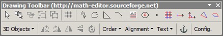 The Drawing Toolbar
The Drawing Toolbar consists in a Microsoft Word template document (files with extension « .dot ») displaying a special command bar to the user. With the various buttons offered, the user can then create simple mathematical figures and choose a proper layout on the page.
The Drawing Toolbar exports many commands that already exist in Microsoft Word but are most of the time not easily accessible to the average user. Other functions have also been implemented for mathematical purposes, such as creating a grid, triangles or graduated lines.
Getting started
Installation
In order to be able to use the Drawing Toolbar, you need to proceed to the following:
- You must allow the execution of macros. In menu Tools, then Macros, then Security, go to the second tab and make sure to check the box Trust Visual Basic Project (or something similar)
- You first need to install it to a special location so that it will be
automatically loaded by Microsoft Word on its startup. Usually, this location is
C:\Documents and Settings\UserName\Application Data\Microsoft\Word\Startup. To be sure, just open the template document, it should tell you where to copy it. - Verify that the template is a global template. To do so, in the « Tools » menu, click on « Templates and add-ons » (or something similar, I don't have Word in English), then verify that the checkbox for the template is effectively checked.
- You must then restart Microsoft Word. If everything went right, you should have a new button called Drawing in the standard command bar.
Built-in Microsoft Word functions
Grouping and Ungrouping
Regrouping graphical objects enables to handle them as a single entity, so that this entity can be easily positioned on the document. I remarked that only few people use the grouping functions when drawing figures, causing terrible loss of productivity when things have to get moved inside the document or between documents.
| Button | Description of the button |
|---|---|
 | Groups selected objects into a single entity. |
 | Ungroups the entity (needed in case you want to modify the entity). |
Simple objects
| Button | Description of the button | ||||||||||||||||
|---|---|---|---|---|---|---|---|---|---|---|---|---|---|---|---|---|---|
 | Draws a line "hand-free". When wanting to emulate a hand-free drawing, first draw it using lines, rectangles, etc, then redraw on your existing figure with this tool.
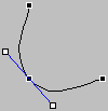
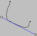
Click here to popup an example of this functionality (you need to have Javascript active). Drawing with the hand-free toolThe Hand-Free Tool is the most powerful drawing tool of Microsoft Word. It enables drawing lines, broken lines, really hand-free parts, closed and opened curves and many other things. The first step consists in the drawing of the control points of the curve. In order to draw a straight line, you just need to click, then release the mouse. In order to draws a curve, you just need to click, then maintain the mouse button down. In order to finish the curve, you just need to click twice at the same place (this will create an opened curve), or to click twice where you started drawing the curse (this will create a closed curve).
Example of closed curveIn this example we will create a curve in four steps:
| ||||||||||||||||
 | Creates an opened or closed curve with linear, curved or hand-free borders. | ||||||||||||||||
 | Creates a rectangular triangle. | ||||||||||||||||
 | Creates an arc of an ellipse (or of a circle if the "Shift" key is down). Useful for noting angles between segments. | ||||||||||||||||
 | Creates an ellipse (or a circle if the "Shift" key is down). |


Rotational or symetrical transformations
| Button | Description of the button |
|---|---|
 | Rotates the object of a quarter to the left. |
 | Rotates the object of a quarter to the right. |
 | Rotates the object to as wanted. You may also change the angle by viewing the properties for the object (see the "Size" tab). |
 | Does a symetry with the vertical as reference. |
 | Does a symetry with the horizontal as reference. |
Positioning in the document
These tools enable to choose the position of the figure on the document.
By default, the figure is placed over the text. Because of that, many users add newlines in the document in order for the figure to not be over the text, but this is not a nice solution. One should better use the figure positioning capabilities of Microsoft Word.
| Button | Description of the button |
|---|---|
| Text | Menu enabling figure and text positioning. By default, when objects are grouped, the positioning is of the figure is over the text. |
 | (Text Menu) Forces the text to surround the figure with some margin. |
 | (Text Menu) Forces the text to surround the figure without any margin. |
 | (Text Menu) Forces the text to lay before and after the figure. |
 | (Text Menu) Forces the figure to be under the text. |
 | (Text Menu) Forces the figure to be over the text. This is the default positioning. |
 | (Text Menu) Forces the text to lie left and right to the figure. |
 | (Text Menu) Forces the text to lie left only to the figure. |
 | (Text Menu) Force the text to lie right only to the figure. |
 | (Text Menu) Forces the text to lie where there is more space. |
| Alignment | Menu enabling figure positioning against other figures or the page. |
 | (Alignment Menu) Bottom-Aligns the objects. |
 | (Alignment Menu) Top-Aligns the objects. |
 | (Alignment Menu) Left-Aligns the objects. |
 | (Alignment Menu) Right-Aligns the objects. |
 | (Alignment Menu) Horizontally-Aligns the centers of the objects. |
 | (Alignment Menu) Vertically-Aligns the centers of the objects. |
 | (Alignment Menu) Rearranges the objects horizontally (horizontal spacing becomes identical between objects). |
 | (Alignment Menu) Rearranges the objects vertically (vertical spacing becomes identical between objects). |
 | (Alignment Menu) If this button is pressed, the buttons above act with the document layout as a reference. |
Other useful stuff
| Button | Description of the button |
|---|---|
 | Duplicates (clones) the currently selected object. This can also be done by pressing the "Shift" key while dragging the object. |
 | Shows a panel enabling enforcement of objects positioning on an invisible Microsoft Word grid. Sometimes, it is quite useful to deactivate the grid when you want to draw an object at a very specific place on the document (for example when drawing an arc). |
 | Anchors or removes the anchor of the currently selected object. Every object has an anchor that helps Microsoft Word to determine where the object lies compared to the current paragraph. When an object becomes anchored to some piece of text, the object will move with the text, but also it is still possible to move the object on the document, however, the object will remain anchored to the text. |
New functions
Adding text letters to a figure
| Button | Description of the button |
|---|---|
 | Inserts a borderless text area of 1 square cm with a letter in it. |
 | Inserts a letter surrounded by a 1 cm diameter circle (useful to number figures). |
 | Inserts a dot of 1 mm diameter. |
Grid and graduates lines
These tools enable the creation of grids and graduated lines with many user-specified parameters.
| Button | Description of the button |
|---|---|
 | Inserts a grid.
Click here to popup an example of this functionality (you need to have Javascript active).
Warning:
This tool is programmed in VBA, hence the creation of the figure takes some time, so be patient.
 The Grid panel
By pressing the Grid button, a preference panel pops up enabling to modify the following parameters:
The following example illustrates this functionality:
|
 | Inserts a XY Axis.
Click here to popup an example of this functionality (you need to have Javascript active).
Warning:
This tool is programmed in VBA, hence the creation of the figure takes some time, so be patient.
 The XY Axis panel
By pressing the XY Axis button, a preference panel pops up enabling to modify the following parameters:
The following example illustrates this functionality:
|
 | Inserts a graduated horizontal line (X Axis).
Click here to popup an example of this functionality (you need to have Javascript active).
Warning:
This tool is programmed in VBA, hence the creation of the figure takes some time, so be patient.
 The Graduated Line panel
By pressing the Graduated Line button, a preference panel pops up enabling to modify the following parameters:
The following example illustrates this functionality:
|


Geometrical 2D and 3D figures
| Button | Description of the button |
|---|---|
 | Inserts a triangle in real size. |
 | Inserts an arc of an ellipse (or of a circle) defined by its radiuses and its angle.
Click here to popup an example of this functionality (you need to have Javascript active).
Warning:
This tool is programmed in VBA, hence the creation of the figure takes some time, so be patient.
 The Arc of Ellipse panel
By pressing the Arc of Ellipse button, a preference panel pops up enabling to modify the following parameters:
The following example illustrates this functionality: the result is an arc of circle of 150° with a radius of 3 cm:
|
| 3D Objects | Inserts predefined 3D objects. |

Copyright ©2005-2007 Renaud Métrich
Thanks to for Web Page hosting.
